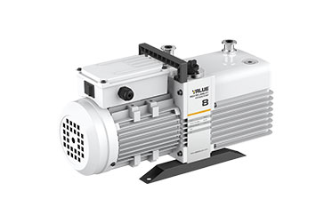
The rotary vane vacuum pump is mainly used for vacuum pumping. It is composed of several parts including a rotor, vanes, bearings, and seals. As a vacuum pump applied in the industrial food industry, it has advantages such as low noise and high efficiency.

High pumping speed, small size, lightweight, low noise, easy maintenance, and high ultimate vacuum. According to international standards, the ultimate vacuum is 6×10⁻²Pa (i.e., 5×10⁻⁴Torr, note: Torr=133.32Pa).
Equipped with a composite screw with a vent valve and an oil inlet hole. The dual-stage rotary vane pumps produced in our country for many years have the oil inlet hole designed on the lower exhaust valve seat inside the oil tank. When the oil hole is blocked, the oil needs to be drained, and the oil tank removed to unblock the oil hole. With the vacuum pump, simply unscrew the composite screw to unblock the oil hole, and also discharge debris and water vapor. This is quick and effortless, greatly improving the pump's working efficiency.
The rotary vane pump consists of a rotor mounted eccentrically within a stator chamber and two or several vanes located in the rotor slots. The rotor either tangentially or intersectingly touches the inner surface of the pump housing. When the rotor drives the vanes to rotate, the vanes, aided by centrifugal force (and sometimes spring force), closely adhere to the cylinder wall, separating the intake and exhaust ports. This causes the intake chamber to expand periodically, thus inhaling air, while the exhaust chamber volume periodically decreases, compressing the gas. The pressure of the gas and oil pushes open the exhaust valve, thereby achieving vacuum.
The dual-stage pump comprises two single stages in series. When the intake pressure is high, generally in medium to large pumps, the second stage can simultaneously expel gas. When the intake pressure is low, the gas is first expelled from the high stage to the low stage, and then expelled outside the pump.
Due to the compression process involved in the vacuum pump's inhalation, when dealing with condensable gases like water vapor, if the vapor reaches its saturation pressure before being expelled from the pump chamber, it will condense in the oil, causing emulsification and degradation of the pump oil, impairing lubrication and sealing performance. The condensates can also revert to gas in the intake chamber, reducing the vacuum level. It is reported that with water content exceeding 50%, lubrication can be compromised, necessitating frequent oil changes and wasting resources. After eighteen years of research, foreign countries developed the gas ballast pump. Its principle is that the pressure in the exhaust chamber is composed of the partial pressure of air and steam. Exhaust occurs only when the combined pressure overcomes the atmospheric pressure and spring force of the exhaust valve. The gas ballast valve introduces a certain amount of air into the exhaust chamber before exhaust occurs to reduce the steam partial pressure within the exhaust pressure. When it drops below the saturated vapor pressure at the pump temperature, the vapor can be expelled with the introduced gas, thus avoiding condensation in the pump oil. Furthermore, during closed pump operation, condensable gas already mixed in the oil can dissolve into the substances in the oil and volatilize, potentially escaping from the oil within the pump chamber. If the gas ballast is then activated, a certain amount of condensable substances can be expelled, effectively purifying the pump oil and extending its usage period. Since vacuum pump oil is expensive and limited in supply, reasonable use of the gas ballast valve has significant economic implications.
Structurally, the gas ballast valve has a check valve to prevent oil and gas from escaping through the gas ballast hole during exhaust. The gas ballast amount can be adjusted to achieve different gas ballast limit pressures, and the valve can be positioned outside the pump for remote operation. When the gas ballast valve introduces micro-leaks, noise can be reduced, and it can also act as a vent valve upon pump shutdown, preventing or delaying oil backflow.
The gas ballast amount relates to the pump's geometrical pumping speed, the geometrical volume of the gas ballast stage, the size of the gas ballast hole, and the gap size. The gas ballast limit pressure relates to the pump's non-gas ballast limit pressure and the oil circuit design, and also to the gas ballast amount. For the same pump, opening the gas ballast decreases ultimate pressure and pumping efficiency while increasing pump temperature. Smaller gas ballast changes have lesser impacts, and the amount of condensable gas expelled is also less.
Additionally, higher exhaust temperatures increase the saturated vapor pressure at the exhaust temperature, allowing for a higher maximum permissible inlet steam pressure and greater allowable water vapor. Thus, when the pump's system contains more water vapor, it is advisable to let the pump run idle for about 20 minutes until the pump temperature rises before evacuating the system. This can prevent or reduce water vapor condensation within the pump. For water-cooled pumps, a temperature control device can be used to maintain the pump temperature within a safe yet relatively high range.
For example, for a 150L/s single-stage rotary vane pump, controlling the pump temperature at 75±5°C allows a permissible water vapor amount of 12-14kg/h. Rotary vane vacuum pumps require regular maintenance to prolong their service life. Regular replacement of vacuum pump oil ensures the proper functioning of the rotary vane vacuum pump. To ensure the stable operation of the rotary vane vacuum pump, use it in an environment free from debris accumulation to prevent foreign substances from being drawn into the pump. Generally, rotary vane vacuum pumps can be repaired if damaged, but maintenance and repairs should be carried out by professional technicians.